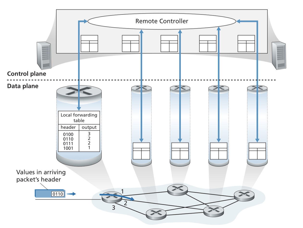
An approach taken in the The Network Layer where a physically separate, remote controller computes and distributes the Flow Tables to be used by each Packet Switch.
This approach separates the network layer into:
- Control plane: Logic deciding how traffic are forwarded, handled by the controller.
- Data plane: hardware or software that performs the forwarding of packets, handled by the Packet Switches.
It is software-defined because computing of forwarding tables are done in software.
Controller Functionality
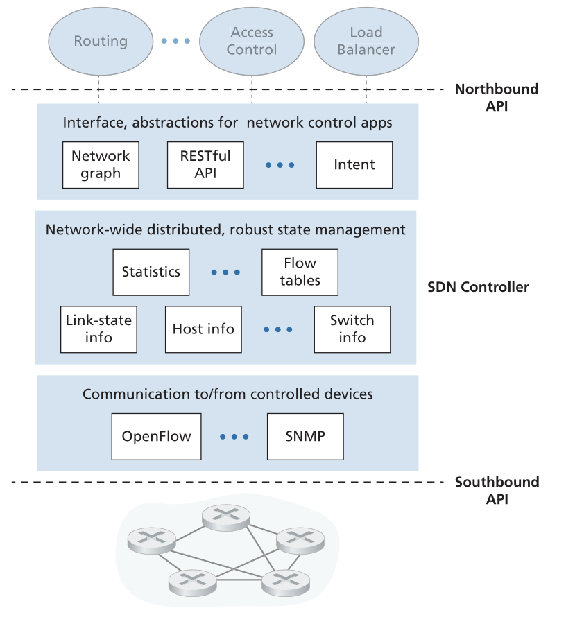
Can be organised in three layers ordered from southbound- to northbound-API (bottom up):
Communication layer: used for communicating between controller and switches. Almost all controllers use OpenFlow for this.Network-wide state-management layer: used for logic involving the construction of Forwarding Tables, e.g. firewall rules, information about the switches etc. Also stores the constructed forwarding tables.Interface to the network-control application layer: Interacts with network-control applications by allowing them to read/write state and Flow Tables within the network-wide state management layer.
Examples
How the controller handles a failed link
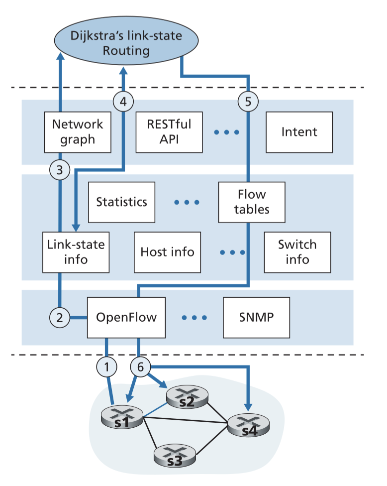
- Switch s1, experiencing a link failure between itself and s2, notifies the SDN controller of the link-state change using the OpenFlow port-status message.
- The SDN controller receives the OpenFlow message indicating the link-state change, and notifies the link-state manager, which updates a link-state database.
- The network-control application that implements Dijkstra’s link-state routing (previously registered to be notified when link-state changes) receives the notification of the link-state change.
- The link-state routing application interacts with the link-state manager to get updated link state; it might also consult other components in the state-management layer. It then computes the new least-cost paths.
- The link-state routing application then interacts with the flow table manager, which determines the flow tables to be updated.
- The flow table manager then uses the OpenFlow protocol to update flow table entries at affected switches—s1 (which will now route packets destined to s2 via s4), s2 (which will now begin receiving packets from s1 destined to s2), and s4 (which must now forward packets from s1 destined to s2).